Meg Process Flow Diagram Concept Diagram Of The Meg System U
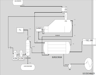
Magnetoencephalography (meg) Meg injection dehydration teg campbell vs system plant 2007 tip figure copyright john company Process flow diagram for meg regeneration with phe reboiler (fjords
Schematic illustration of MEG analyses at the individual subject level
Meg data collection and analysis. (a) the signals detected at the meg | meg processing pipeline. (a) resting state meg sensor data is Megohmmeter working principle
(color online) physical view of meg process [21]
Dehydration meg process teg injection gas diagram vs flow water separation liquid gif lean vapor filtration(a) schematic illustration of the process of meg preparation. the rgo Aramco outlines best practices processfor sour-gas feed meg systemNew meg production process.
Meg phe regeneration reboiler fjordsMeg undergoing Meg signals detected sensorsOverview of the meg reclaiming unit.
![(Color online) Physical view of MEG process [21] | Download Scientific](https://i2.wp.com/www.researchgate.net/publication/271918554/figure/fig5/AS:668773845590016@1536459518324/Color-online-Physical-view-of-MEG-process-21.png)
Improving plant throughput using thermax chillers for meg process
Monoethylene glycol(meg) plant, meg production plant and meg productionMeg phe fjords regeneration reboiler Meg process flow regeneration chart processing gas sheetMeg principles conventional signal.
Meg reclaimingImpact of heavy end on the performance of a mechanical refrigeration Process flow sheets: meg regeneration process with flow chart1: scheme of the time-scale of the meg process..

Process flow sheets: meg regeneration process with flow chart
Process flow diagram for meg regeneration with phe reboiler (fjordsConcept diagram of the meg system used in the study and hela results Refrigeration injection meg economizerSchematic of meg data preprocessing and analyses. (a–d) standardized.
Meg plant production process technology system know acetic acid do application development sl provided advantages tec follows has previous next| working mechanism of the meg process. Working mechanism of the meg process.Meg regeneration process flow chart processing gas sheet natural.

Person undergoing an meg process. source: www.wikipedia.com.
Meg data processing flowchart. raw meg data are initially...Meg-graph process visualisation Meg adaptedMegohmmeter megger diagram circuit principle working electrical fig.
Basic principles of signal generation in a conventional adult megSchematic illustration of meg processing pipelines. coloured columns Schematic illustration of meg analyses at the individual subject level7: block diagram of a typical meg system. adapted from sternickel and.

Meg injection vs. teg dehydration
Meg workflow ntu magnetoencephalographyComplete process flow diagram of the sulphuric acid production process Meg processing pipeline resting sensorMeg indicate pipeline arrows.
Meg process production plant flow diagram plants technology glycol facilities egMeg recording and analysis pipeline. arrows indicate steps in time Meg injection vs. teg dehydrationGas dehydration process (meg, teg) : 네이버 블로그.


